Conference Microphone System
Basic Information
Used for conferences, committees, or board member-type meetings. Can accommodate up to 24 individual members. These are condenser microphones and DO REQIURE phantom power; however, the accompanying Central Unit supplies this power requirement.
Setup Considerations
The system consists of equipment from BOTH rack cases (1 of 2 and 2 of 2).
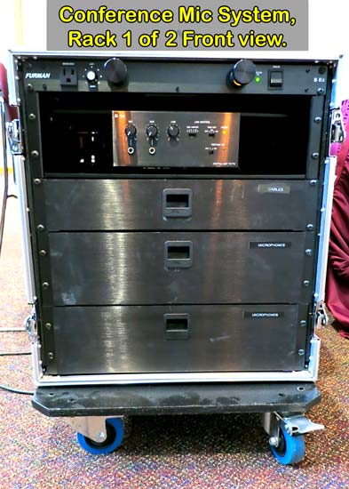
Rack 1 of 2: Front View
| Storage | Open | What's Inside |
|---|---|---|
 |
|
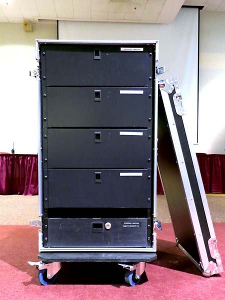
Rack 2 of 2: Front View
| Storage | Open | What's Inside |
|---|---|---|
 |
|
Basic setup instructions:
- Remove both the front and back case lids from rack #1.
- Remove the front case lid from rack #2. There is no need to remove the back case lid of rack #2.
- From rack 2 of 2: Remove CHAIRMAN unit(s) from the drawer labeled CHAIRMAN UNITS and REMOTE DELEGATE. Place the CHAIRMAN unit(s) in the center of the main or front table(s). These have a special function and are used by persons leading the meeting.
- From rack 2 of 2: Remove the DELEGATE units from their drawers labeled DELEGATE UNITS. Place one unit on the table in front of each chair at the table.
- From rack 1 of 2: Remove microphones from their drawer(s) labeled MICROPHONES. Connect a microphone to the microphone input at the top of each DELEGATE and CHAIRMAN unit.
- From the seated perspective of the table, and beginning with the left-most unit and microphone on the main/front table: Connect the cable attached to the DELEGATE or CHAIRMAN unit to the female input connection of the unit that is positioned to the right of the current unit.
- Moving left-to-right or counterclockwise, continue connecting the attached cable from one unit to the female input connection of the unit to the right of the current unit. Do this until you have reached the final unit and microphone.
- Connect the attached cable of the final unit and microphone to Line 1 at the rear of rack 1 of 2 (use an extension cable from rack 1 of 2 if necessary).
- From the rear of rack 1 of 2: Plug the power cable into an eletrical socket (use an AC extension cable if necessary).
- From the front of rack 1 of 2: Power on rack 1 of 2 by pressing the top part of the main power toggle switch upward on the power conditioner at the top of the rack. The amplifier unit should power on.
- From the rear of rack 1 of 2: Plug a microphone (XLR) cable into the MAIN OUTPUT connection. Connect the other end of the microphone cable into the sound system.
- IMPORTANT! On the Central Unit and with the main sound system turned OFF: Test EACH microphone by moving the TEST/MIC ON switch to the right to the ON position. A red light will illuminate on the Central Unit, and EACH DELEGATE or CHAIRMAN unit and microphone will illuminate.
- Once you have VERIFIED that ALL of the mics are lit and are working correctly, move the Central Unit's TEST/MIC ON switch to the left to the OFF position.
- IMPORTANT! Test the volume level of the conference mic system through the room's sound system. Adjust the volume of the mic system so that no feedback is heard by using the volume knobs of the room's sound system.
See also Student / CGA Senate Meeting setup.
