
B.U.S.T.E.D. Event Setup
B.U.S.T.E.D. is a theatrical event organized by BU's Residence Life Office. The event's setup and operation is generally the same for each performance.
Main equipment required for this event:
- Large sound system with large stage rack
- Speakers
- Choral Microphones
- Theatrical lighting and lighting controller (prefocused)
- Two Shure wireless handheld mics from the large sound system
Setup steps required to setup and run this event:
- Focus theatrical lighting as a stage wash.
- Transfer all technical equipment from storage locations to the Ballroom.
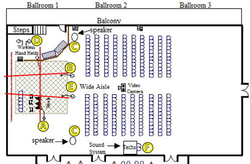
- Position/set the equipment in the locations shown on the setup diagram (Figure 1)
-
- A= Choral Mics on stage left and stage right.
- B= Choral Mics at the front of the stage, or downstage.
- C= Speakers on speaker stands at both house left and house right.
- D= Two Shure wireless handheld mics from the large sound system on boom mic stands backstage.
- E= The large stage rack under the front of the stage.
- F= Large sound system rack at front of house (FOH).
- Connect all audio, Ethernet, and power cables.
- TEST all connections. (see Equipment Setup Specifics below)
- Ensure all connections and signals work.
- Tape down cables in house area for safety.
- Always replace batteries with new batteries despite the charge of the current batteries.
- Using white label tape and a Sharpie, label what mics are at which channels on the board.
Equipment Setup Specifics
- At the large sound system rack (F)- Connect the two red Shure wireless mic (WL #1 and WL #2) cables from the rear of the rack into the board's mic input channel 1 and channel two, respectively (WL #1 connects to Channel 1, WL #2 connects to channel 2).
- At the large sound system rack (F)- Ensure that the thin mic cables for channel numbers 3-6 at the rear of the rack from the Whirlwind mic input device are connected, respectively, to board mic input numbers 3-6.
- At the four Choral mics (A&B) and Stage Rack (E)- Starting at STAGE RIGHT (house left), connect the 1st stage right choral mic output to the Stage Rack input #3. Next, connect the front (downstage) STAGE RIGHT choral mic output into the Stage Rack input #4. Then, connect the front (downstage) STAGE LEFT choral mic output into the Stage Rack input #5. Finally, CONNECT THE stage left (house right) choral mic output to the Stage Rack input #6.
- At the Stage Rack (E)- Use a 50ft orange-painted mic cable to connect the Whirlwind mic OUTPUT "A" to the INPUT of the STAGE RIGHT (house left) speaker. Next, use a second 50ft orange-painted mic cable to connect the Whirlwind mic OUTPUT "B" to the INPUT of the STAGE LEFT (house right) speaker.
- Connect the gray twenty-five foot (25') Category 5 (Cat5) network cable stored in the rear of the Stage Rack into the blue data jack in Ballroom 1. DO NOT DISCONNECT THE CAT5 CABLE FROM THE NETWORK JACK AT THE REAR OF THE STAGE RACK. CONSTANTLY DISCONNECTING AND CONNECTING THE CABLE CAUSES THE NETWORK JACK TO WEAR PREMATURELY.
- Connect the gray ten foot (10') Category 5 (Cat5) network cable stored in the rear of the FOH rack into the blue data jack on the wall in Ballroom 2. DO NOT DISCONNECT THE CAT5 CABLE FROM THE NETWORK JACK AT THE REAR OF THE STAGE RACK. CONSTANTLY DISCONNECTING AND CONNECTING THE CABLE CAUSES THE NETWORK JACK TO WEAR PREMATURELY.
- Alternate (do not perform steps #5 or #6): FROM the FOH sound system rack TO the stage rack- Run the black Category 5 (Cat5) network cable stored in the rear of the FOH rack along the wall, make a 90 degree angle from the wall to the stage rack. Connect one end of the Cat5 to the network jack at the rear of the Whirlwind device in the STAGE RACK. Connect the other end of the Cat5 cable spool to the blue Cat5 cable from the Whirlwind device in the FOH RACK.
- Turn ON all of the equipment in the following order (IMPORTANT! Power down equipment in reverse order!):
- Both FOH power conditioners
- Stage rack
- Speakers
A. Stage left and stage right choral mics must be parallel to each other and must be aligned in the same positions on either side of the stage. The middle red line represents the area to which the microphones should be focused and aligned. The actual microphone ends at the top should be positioned approximately 2-5 degrees downward and should be focused to a point 2/3 across the stage or 1/3 of the area to the opposite side of the stage.
B. Downstage right and downstage left choral mics must be equidistant from their respective ends of the stage front. The actual microphone ends at the top should be positioned approximately 2-5 degrees downward and should be focused along the other two red lines in Figure 1.
C. House left speaker should be plugged into the electrical socket indicating circuit/breaker #7. House right speaker should be plugged into the electrical socket indicating circuit/breaker #15. Speakers and speaker stands should be positioned as close to the walls as possible. Legs of the speaker stands must be extended as far as possible in order to avoid unstable speakers and stands, and to avoid speakers falling on audience members/attendees. The speakers must be aligned along the same plane. Both speakers must be raised to the same height. Speaker volumes must be the same (either set at 0 or at 9:00. Speaker EQs should be turned off.
D. Wireless mics and wireless mic clips live together. Store the wireless mics with their corresponding mic clips. Remember to change the batteries BEFORE the show begins.
E. The stage rack should be powered by the electrical socket indicating circuit/breaker #42 or #9. DO NOT use the electrical floor pocket socket in the center of Ballroom 1.
F. BOTH power cables for the FOH sound rack should be connected to the electrical socket indicating circuit/breaker #42. Do not use electrical socket indicating circuit/breaker #(7), because there is greater chance of audience members/attendees knocking out the power cables during the event, thus completely stopping the event. Using electrical socket indicating circuit/breaker #42 allows you to monitor and control access to the socket.
Microphone channel organization
Your first six mixing console channels and labels with board tape and Sharpie should be organized as below.
| Channel 1 | Channel 2 | Channel 3 | Channel 4 | Channel 5 | Channel 6 |
| WL #1 | WL #2 | Choral HL | Choral HL Center | Choral HR Center | Choral HR |
Board channel settings
|
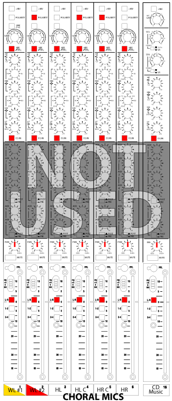
In Figure 2, red boxes represent depressed buttons and red lines represent the direction of the pan knob (centered). The Auxiliary (Aux 1-6) section is not used for BUSTED. Music from a CD is hard wired into channel 16. Channels 3-6 at the mixing console should have these settings (Figure 3) for the Choral mics for the event B.U.S.T.E.D. 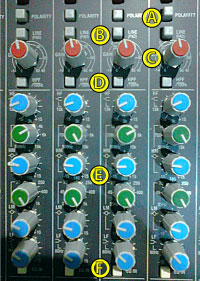
A. Shows polarity settings. B. Shows Line(pad) settings (all four channels have button in upward position). C. Shows gain settings. D. Shows 100Hz cut/high pass settings (all four channels depressed). E. Shows equalization (EQ) settings. F. Shows "EQ in" button settings (all four channels depressed). |